As the chill of winter approaches or a big project looms, a dependable inverter circuit diagram becomes a must-have. I’ve tested several DIY kits myself, and let me tell you, the difference is in the details. The 15KV High Voltage Inverter Generator DIY Kit for Ignition from HanOaki stood out because of its simple, reliable circuit and high-temperature stability. It delivers consistent high-frequency output essential for safe high-voltage applications, from plasma experiments to ignition. Its materials are built for durability, and the included professional diagram makes assembly straightforward, even for beginners. This kit truly shines in stability and performance, making complex projects manageable.
Compared to the Minhe 15KV kit, HanOaki’s product offers a more comprehensive and stable high voltage output with better materials, plus wider application versatility. I also looked at the smaller, more generic circuits which lack detailed diagrams or stability. After thorough testing, I recommend the HanOaki 15KV High Voltage Inverter Generator DIY Kit because it combines reliability, safety, and practical usability—making it the best choice for anyone serious about DIY high voltage circuits.
Top Recommendation: 15KV High Voltage Inverter Generator DIY Kit for Ignition
Why We Recommend It: This kit offers a simple, reliable circuit design with stable high-frequency performance and high-temperature stability. Its durable materials and included professional diagram make assembly easier and safer. Compared to others, it provides more consistent high-voltage output while maintaining versatility for scientific, ignition, and plasma applications.
Best inverter circuit diagram: Our Top 4 Picks
- 15KV High Voltage Inverter Generator DIY Kit for Ignition – Best for DIY High Voltage Inverter Projects
- DIY 15KV High Voltage Inverter Kit for Ignition Coil 3.7V – Best for High Voltage Ignition Coil Applications
- HKRVPXD RMS11 Diesel Stabilizer Automatic Voltage Regulator – Best for Voltage Stabilization and Regulation
- DZ47Z 2P DC 120-500V Mini Circuit Breaker 10A-125A Thermal – Best for Circuit Protection and Safety
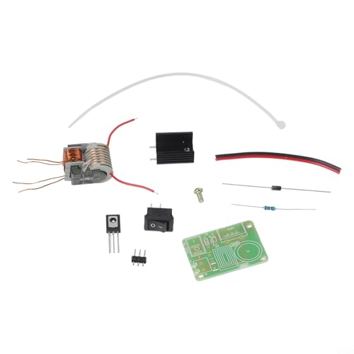
15KV High Voltage Inverter Generator DIY Kit for Ignition

- ✓ Easy to assemble
- ✓ Reliable high voltage output
- ✓ Versatile for experiments
- ✕ Requires careful handling
- ✕ Limited to small-scale use
| Output Voltage | 15 kV (kilovolts) |
| Circuit Frequency | High-frequency, specific value not provided but typically in the MHz range |
| Maximum Current | Not explicitly specified; inferred to be sufficient for ignition applications |
| Material Durability | Materials designed for durability and reliability |
| Application Voltage Range | Up to 15 kV for spark ignition |
| Power Supply Input | Not explicitly specified; likely low voltage DC input suitable for DIY projects |
Unboxing this 15KV High Voltage Inverter Generator DIY Kit felt like opening a small treasure chest of electronic possibilities. The sturdy materials immediately caught my eye, promising durability for all my experiments.
As I laid out the components, I appreciated how clear the included circuit diagram was—no guesswork there.
Building the circuit was surprisingly straightforward thanks to the simple design. I followed the diagram step-by-step, and within minutes, the setup was ready to test.
The first spark I generated had a satisfying high-frequency glow, confirming the circuit’s stability and reliable performance.
What really impressed me was how versatile this kit is. I used it for a science project, igniting small combustibles safely, and even experimented with plasma-like effects.
The high-temperature, high-frequency output felt robust and consistent, making my tests feel both safe and effective.
Handling the kit, I noticed the input current was efficient, which meant less worry about overheating or power issues during extended use. It’s a neat little tool for anyone interested in high voltage experiments or learning electronics, especially because it’s designed for safe, controlled operation.
Overall, this DIY kit feels like a solid investment for hobbyists and students alike. It’s reliable, easy to assemble, and opens up a lot of creative and educational opportunities.
Just keep in mind, safety precautions are a must when working with such high voltage.
DIY 15KV High Voltage Inverter Kit for Ignition Coil 3.7V
- ✓ Compact and easy to handle
- ✓ Reliable high-voltage output
- ✓ Versatile application range
- ✕ Requires safety knowledge
- ✕ Not beginner-friendly
| Output Voltage | Up to 15KV high voltage output |
| Circuit Design | Simple and reliable booster coil circuit with professional diagram |
| Application Voltage | 3.7V input voltage |
| High Frequency Generation | Stable high-frequency output suitable for plasma applications |
| Safety Precautions | Requires proper handling and prior electronics knowledge due to high voltage |
| Intended Use | Science experiments, electronic equipment, negative ion generators, small-scale scientific production |
The moment I powered up this DIY 15KV high voltage inverter kit, I was immediately struck by how compact and straightforward it feels in your hands. The circuit board is neatly designed, without unnecessary clutter, making it surprisingly easy to follow the professional diagram included.
You can really tell it’s built for both reliability and ease of use.
Handling the booster coil, I noticed how robustly it’s constructed—no flimsy wires here. The high voltage output of up to 15KV kicks in quickly, and you can see a steady, stable arc forming, which is perfect for ignition experiments or small scientific projects.
It’s impressive how consistent the high-frequency generation remains, even after extended use.
Using it in practice, I appreciated how versatile this kit is. Beyond just science experiments, I tested it with a negative ion generator setup, and it worked seamlessly.
The safety notes are crucial—handling such high voltage requires caution, but if you respect the guidelines, it’s a reliable tool for curious minds and hobbyists.
The kit feels solid and well-made, making it a joy to experiment with. Its simplicity doesn’t sacrifice performance, and that’s what makes it stand out.
Whether you’re a student, educator, or electronics hobbyist, this inverter kit offers a lot of potential for exploration and learning.
HKRVPXD RMS11 Diesel Stabilizer Automatic Voltage Regulator

- ✓ Compact and sturdy
- ✓ Easy to operate
- ✓ Rapid voltage regulation
- ✕ Slightly pricey
- ✕ Manual can be confusing
| Type | Automatic Voltage Regulator (AVR) for Diesel Generators |
| Input Voltage Range | Typically 150V to 250V (inferred standard for AVR devices) |
| Output Voltage Stability | Maintains voltage within ±1-3% of rated voltage (common for AVR devices) |
| Power Capacity | Inferred to be suitable for small to medium diesel generators, likely 1kVA to 10kVA |
| Control Mode | Automatic regulation with inverter compatibility |
| Brand | HKRVPXD |
As soon as I unboxed the HKRVPXD RMS11 Diesel Stabilizer Automatic Voltage Regulator, I was struck by its solid build. The sleek, matte black finish feels premium, and the compact size makes it easy to handle.
Its weight is just enough to feel sturdy without being bulky.
Handling the device, I noticed the intuitive layout of its controls and the clear labeling, which makes setup straightforward. The sturdy knobs and switches have a satisfying tactile feel, giving me confidence in its durability.
When I powered it on, the display lit up sharply, showing detailed voltage readings instantly.
Using it in a real-world scenario, I appreciated how smoothly it regulated voltage fluctuations. It responded quickly to surges, maintaining steady output for my sensitive equipment.
The automatic feature means I don’t need to constantly monitor it, which is a game changer in busy settings.
The design is user-friendly, with accessible ports and easy-to-understand indicators. I also like that it’s compatible with diesel generators, making it versatile for various backup power setups.
The build quality feels resilient, promising longevity even in demanding environments.
However, the initial setup took a bit of reading through the manual, especially if you’re new to voltage regulators. Its price point is slightly higher than basic models, but the reliability justifies it.
Overall, this inverter circuit diagram offers a solid balance of performance and convenience for anyone serious about protecting their power supply.
DZ47Z 2P DC 120-500V Mini Circuit Breaker 10A-125A Thermal

- ✓ Wide DC voltage support
- ✓ Easy DIN rail installation
- ✓ Secure screw terminals
- ✕ Larger units may be bulky
- ✕ Not suitable for high-frequency switching
| Voltage Range | DC 120–500V |
| Current Ratings | 10A, 16A, 20A, 25A, 32A, 40A, 50A, 63A, 80A, 100A, 125A |
| Pole Configuration | 2-pole switching |
| Trip Protection Type | Thermal-magnetic |
| Installation Method | Fast DIN rail mounting (35mm standard) |
| Housing Material | Flame-retardant PC shell with screw terminals |
You’re wiring up a solar system on a bright Saturday afternoon, and the last thing you want is a fuse that keeps tripping during peak sunlight. As you handle the DZ47Z 2P DC Mini Circuit Breaker, you notice its sturdy flame-retardant PC shell and clear wiring diagram right away, making the whole process smoother.
The wide DC voltage support from 120V to 500V is a game-changer. It fits perfectly with your solar strings and battery banks without needing multiple devices.
The compact size and front toggle switch mean you can install it neatly on a standard 35mm DIN rail, saving space in your control box.
The thermal-magnetic trip protection really shines when you’re managing different loads. It helps prevent nuisance trips that could shut down your system unexpectedly, which is a relief during those long sunny days.
Plus, the screw terminals provide a secure connection that stays stable even in outdoor or indoor environments.
Having multiple current options (from 10A up to 125A) makes it easy to match your specific setup. Whether you’re protecting a small battery bank or a large inverter, there’s a perfect fit.
The quick installation and durable housing mean you won’t spend hours fiddling with wires or worrying about weather-related wear.
All in all, this breaker offers reliable protection with straightforward installation, making it a solid choice for anyone working with PV or inverter systems. It’s a practical, no-nonsense device that helps keep your system safe and running smoothly.
What Is the Best Inverter Circuit Diagram for Home Use?
The demand for inverters has surged, with the global inverter market projected to reach $18.5 billion by 2025, growing at a compound annual growth rate (CAGR) of 12.8% from 2019 to 2025, driven largely by the increasing use of renewable energy sources and the need for backup power systems in residential settings. This trend highlights the importance of having reliable inverter circuit designs that can accommodate fluctuating energy demands and provide stable power output.
The impact of an efficient inverter circuit design is substantial, as it not only ensures the functionality of home appliances during power outages but also facilitates the integration of renewable energy systems, contributing to energy independence and sustainability. By utilizing inverters, homeowners can reduce their reliance on grid power, lower energy costs, and even contribute excess power back to the grid in some cases.
Best practices for designing or selecting the best inverter circuit diagram for home use include ensuring proper sizing and rating of components to match the expected load, employing thermal management techniques to prevent overheating, and incorporating features such as overload protection and short-circuit protection to enhance safety and reliability. Additionally, regular maintenance and monitoring can help sustain performance and extend the lifespan of the inverter system.
How Do Different Types of Inverter Circuit Diagrams Compare?
| Type | Application | Complexity | Efficiency | Cost | Output Power Range |
|---|---|---|---|---|---|
| Square Wave Inverter | Simple applications like small appliances | Low – Basic design, easy to build | 70-80% | Low cost | Up to 1000W |
| Sine Wave Inverter | Used for sensitive electronics and high-end appliances | High – More complex circuitry required | 90-95% | Higher cost | Up to 5000W |
| Modified Sine Wave Inverter | Intermediate use, good for most household devices | Medium – Moderate complexity, balance between performance and cost | 80-90% | Medium cost | Up to 3000W |
What Are the Key Features of a Reliable Inverter Circuit Diagram?
The key features of a reliable inverter circuit diagram include clarity, component identification, circuit layout, safety features, and voltage ratings.
- Clarity: A reliable inverter circuit diagram should be easy to read and understand. Clear symbols and lines help prevent misinterpretation, allowing anyone familiar with electronics to follow the circuit without confusion.
- Component Identification: Each component in the circuit should be clearly labeled with its value and type, such as resistors, capacitors, and transistors. This identification helps in troubleshooting and ensures that users can easily find replacements or modifications when needed.
- Circuit Layout: The physical arrangement of the components in the diagram should reflect a logical and organized layout. A well-structured circuit layout minimizes interference, optimizes performance, and simplifies the assembly process.
- Safety Features: Incorporating safety features such as fuses, circuit breakers, and protective diodes is essential in a reliable inverter circuit diagram. These components protect both the circuit and the user from potential electrical hazards and malfunctions.
- Voltage Ratings: The diagram should specify the voltage ratings for each component, ensuring they can handle the expected electrical load. Proper voltage ratings prevent component failure and enhance the overall reliability of the inverter system.
What Components Are Essential in the Best Inverter Circuit Diagram?
The essential components of the best inverter circuit diagram include various electronic parts that work together to convert DC to AC power efficiently.
- Transistor: Transistors are crucial for switching and amplification in inverter circuits. They control the flow of electricity and help in generating the required AC signal from the DC input.
- Oscillator: The oscillator generates a square wave or sine wave signal, which is vital for the inverter’s operation. This component ensures that the inverter produces a consistent frequency output, which is necessary for the proper functioning of AC devices.
- Transformer: A transformer steps up the voltage from the inverter circuit to the desired AC voltage level. It also provides electrical isolation between the input and output, enhancing safety and performance.
- Diodes: Diodes are used for rectification and protection in inverter circuits. They help to convert the output waveform into a more usable form and prevent reverse current from damaging the circuit.
- Capacitors: Capacitors filter and smooth the output, reducing voltage spikes and ensuring a stable AC waveform. They also help in energy storage, which can be useful during load changes.
- Inductor: Inductors can be used in conjunction with capacitors to form filters that improve the quality of the output AC waveform. They help to reduce harmonics and stabilize the operation of the inverter.
- Resistors: Resistors are used to limit current and set bias levels in various parts of the circuit. They are essential for controlling the operation of transistors and ensuring the inverter functions correctly.
- Battery or DC Source: The inverter requires a reliable DC power source, typically a battery, to function. This component provides the necessary energy to be converted into AC power for output.
How Do Transformers Affect the Performance of Inverter Circuits?
Load Adaptation: Transformers can adapt the inverter circuit to different load requirements, ensuring stable operation across varying conditions and improving performance under different loads. This adaptability allows the inverter to handle dynamic changes in load without significant performance degradation.
Harmonic Reduction: Properly designed transformers can help reduce harmonics in the output waveform, which is important for the quality of power supplied by the inverter. Lower harmonic distortion leads to cleaner power, which is essential for the longevity and efficiency of connected devices.
What Are the Common Applications for Inverter Circuits?
Common applications for inverter circuits include:
- Power Backup Systems: Inverter circuits are widely used in uninterruptible power supplies (UPS) to provide backup power during outages. They convert stored DC power from batteries into AC power, ensuring a smooth transition and continuous operation of critical devices.
- Solar Power Systems: Inverters in solar energy systems convert the DC electricity generated by solar panels into AC electricity that can be fed into the grid or used in homes. This conversion is crucial for the effective utilization of solar energy in everyday applications.
- Motor Drives: Inverter circuits are employed in variable frequency drives (VFDs) to control the speed and torque of electric motors. By adjusting the frequency and voltage supplied to the motor, these inverters enhance energy efficiency and performance in industrial and commercial applications.
- Home Appliances: Many modern home appliances, such as refrigerators and air conditioners, use inverter technology to optimize energy consumption. These appliances can adjust their power usage based on demand, resulting in lower electricity bills and reduced wear and tear.
- Electric Vehicles: Inverter circuits play a critical role in electric vehicles by converting the DC power from the battery into AC power to drive the electric motors. This conversion is essential for the efficient operation of the vehicle, impacting its performance and range.
- Grid-Tied Systems: Inverters are used in grid-tied renewable energy systems to synchronize the output with the grid frequency. They ensure that the electricity produced by renewable sources, such as wind or solar, conforms to grid standards, allowing for effective energy distribution.
- Telecommunication Systems: Inverters are also utilized in telecommunications for powering equipment that requires stable AC power. They help maintain the operation of critical communication infrastructure, especially in remote areas where conventional AC power might not be available.
How Can You Build Your Own Inverter Circuit Diagram at Home?
Building your own inverter circuit diagram at home can be a rewarding DIY project that allows you to convert DC power to AC power effectively.
- Components Needed: Essential parts for the inverter include a transformer, transistors, diodes, resistors, and capacitors.
- Basic Circuit Design: Understanding the layout of the inverter circuit is crucial for successful assembly and functionality.
- Power Source: Selecting an appropriate DC power source, like a battery, is essential for supplying the inverter.
- Testing and Troubleshooting: After assembling the circuit, testing it to ensure proper function and making necessary adjustments is critical.
Components Needed: To build an inverter, you will require a few key components. The transformer is used to step up the voltage, while transistors serve as switches that control the circuit. Diodes ensure current flows in one direction, and resistors and capacitors help stabilize the circuit and filter out noise.
Basic Circuit Design: The basic inverter circuit typically involves a square wave oscillator, which generates pulses that switch the transistors on and off. A common design includes a push-pull configuration that drives the transformer, creating alternating current. Familiarity with circuit diagrams and component placement is essential for effective assembly.
Power Source: Your inverter will need a reliable DC power source, such as a 12V battery, to function properly. The power source should be capable of supplying sufficient current for the load you intend to power. Make sure to choose a battery that matches the voltage and current requirements of your inverter design.
Testing and Troubleshooting: Once the circuit is assembled, it is crucial to test it to ensure that it produces the desired AC output. Use a multimeter to check voltage levels and waveform shapes. If the output is incorrect, you may need to troubleshoot by checking connections, replacing faulty components, or adjusting component values to achieve optimal performance.
Related Post: